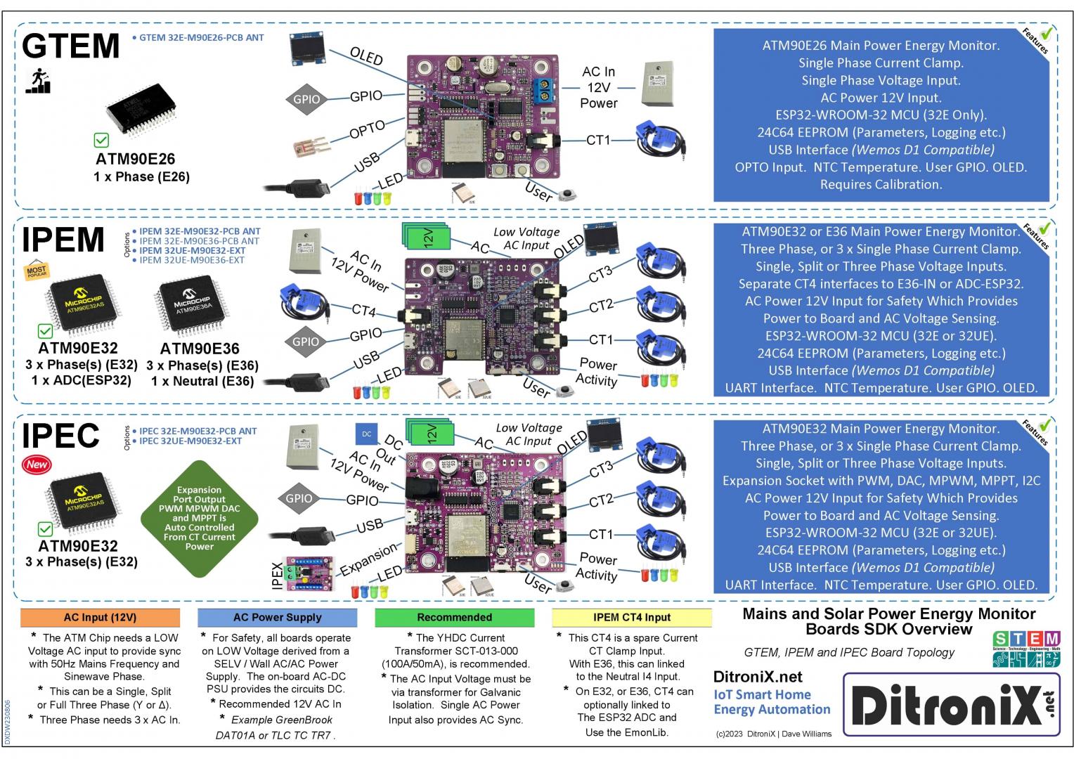
GTEM ESP32 ATM90E26 – Snippets
The ATMEL M90E26 is a high-performance wide-span energy metering chip. The design includes ADC and DSP technologies to ensure the chip’s long-term stability over variations in grid and ambient environmental conditions.
- Power Requirements
- DC 3.3V ~ 6mA
- Clock
- 8.192 MHz – External Crystal
- Interfaces
- SPI (Full Duplex, Synchronous Channel – 3 or 4 wire)
- 3 Wire. /CS Low
- 4 Wire. /CS High to Low on each read/write
- Connected to GTEM ESP32 (GPIO 5/18/19/23)
- UART (2400 or 9600 Baud)
- Connected to GTEM ESP32 UART2 (GPIO 16/17)
- SPI (Full Duplex, Synchronous Channel – 3 or 4 wire)
- Input Voltage Ranges
- I1 = 120uV to 600mV RMS [When Gain is 1, or 5uV to 25mV RMS when Gain is 24] (GTEM connects to CT Clamp jack socket)
- I2 = 120uV to 600mV RMS (GTEM Not used but goes to header)
- VP = 120uV to 600mV RMS (GTEM connects to _ACV_IN_ AC Input via potential divider)
- VN = 120uV to 600mV RMS (GTEM Not used)
- ADC Resolution
- 16 bit
- Accuracy
- Will vary slightly from board to board and setup to setup. Depends on:
- ATM90E26
- Accuracy of 0.1% for active energy and 0.2% for reactive energy over a dynamic
range of 5000:1, is quoted - Electrical parameters measurement: less than ±0.5% fiducial error for Vrms, Irms,
mean active/ reactive/ apparent power, frequency, power factor and phase angle - Phase angle calibration- phase shift
- In calibration, the only practical method is to adjust for unity power factor with a pure resistive load
- i.e. No reactive components at all – so no motors and no electronic switch modes etc
- The reactive power from the M90E26, if there are no phase errors, should read as 0.
- Reactive power can be considered wasted energy
- Accuracy of 0.1% for active energy and 0.2% for reactive energy over a dynamic
- CT Clamp
- Used to measure AC current.
- Standard current transformer clamps to sample current, will vary in output slightly
- Even if moving the CT in different positions of a live cable
- Not ideal for low current loads
- On a meter mA range, used to measure the secondary current, the accuracy up to ±(1.5%
+ 5 digits), or between 2.4% and 3.2% depending on the reading. - Potential slight phase shift, which may vary depending on current amplitude
- Low RMS voltages (mV), which can get influenced by noise, at low currents
- AC (Isolation) Transformer
- Provides AC waveform reference for accurate Real Power measurements
- Used to measure AC Voltage
- Differs from manufacturer to manufacturer
- Need to ensure transformer does not go into saturation
- Example flattening seen at the sine waveform peaks
- Select transformers with cleaner sinewaves
- If a scope if available, check the ZX (Zero Crossing), output
- Potential slight phase shift
- Resistance
- Accuracy of the connected circuit resistors. e.g. Burden Resistor and potential dividers.
- Resistors are typically of 1% tolerance.
- ATM90E26
- Will vary slightly from board to board and setup to setup. Depends on:
- Outputs
- CF1 Active Energy Pulses (Normally Low)
- Can be used for calibration
- Reading the RevP/RevQ bit of EnStatus register 0x46
- Connected to Green LED on GTEM and ESP32 GPIO 34
- CF2 Re-Active Energy Pulses (Normally Low)
- Can be used for calibration
- Reading the RevP/RevQ bit of EnStatus register 0x46
- Connected to:
- Amber LED on GTEM
- GTEM ESP32 GPIO 35
- IRQ Monitors System Status (Normally Low)
- Examples, goes High upon
- Metering / measurement parameter errors
- Active/reactive energy direction changes
- Voltage Sag
- Metering Line Change in Anti-Tamper Mode
- Max 5mA Load
- Can be acquired via System Status register 0x01
- Connected to GTEM ESP32 GPIO 13
- Examples, goes High upon
- WO Warning Out (Normally Low)
- High when Voltage Sag detected via SagWo, register 0x02
- Fatal Error
- Max 5mA Load
- Connected to GTEM ESP32 GPIO 27
- ZX Zero Crossing
- 5ms High Level when voltage crosses zero
- Programmable
- Max 5mA Load
- Connected to GTEM ESP32 GPIO 32
- CF1 Active Energy Pulses (Normally Low)
- Inputs
- CS
- Active Low
- I1 (P/N)
- Current Transformer, CT (On GTEM)
- I2 (P/N)
- Unused 9 (On GTEM)
- VN
- Unused 9 (On GTEM)
- VP
- AC Mains Low Voltage Sample
- Max 600mV RMS via Potential Divider
- Fed via isolated supply AC Mains transformer
- Reset
- M90E26 can be reset when 0x789A is written to software reset register, SoftReset 0x00
- User Select
- High = UART Interface
- Low = SPI Interface
- Metering Mode
- MMD0 and MMD1 are used to select the metering mode
- GTEM solder pad links are provided on the PCB bottom.
- CS
- Registers
- CalStart register 0x20, is 0x6886 after power reset. It should be set to 0x5678 when calibration is required.
- CalStart register 0x20, should be set to 0x8765, after calibration.
Important Foot Note.
These Wiki pages are MOVING to the GitHub Wiki. Simply select a repository pertaining to the board and click Wiki.
Other Details
Further information on this product may be found in our downloads and Wiki pages. Other technical information and code examples are also shared in our GitHub Pages. Project information may also be found on Hackster.io
We value our customers and should you have any other questions, please feel free to contact us.