Description
Features
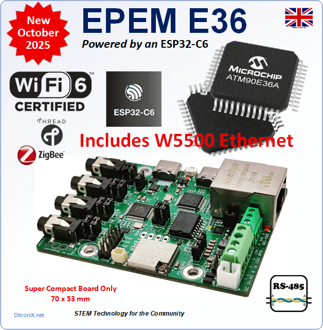
What is EPEM?
EPEM is an acronym for Ethernet, Power Energy Monitor
EPEM is a compact and powerful STEM Community board which is designed for IoT monitoring of mains power circuits.
Video
What is a Power Energy Monitor?
A power energy monitor is a device that safely samples the AC voltage and current flow, from one, or more, electrical phases, and from this, derives a range of accurate mains power measurements which can then be used for smart metering, or energy monitoring purposes.
These individual measurements can then be extrapolated into a range of useful real-time data such as total RMS power, active, re-active power, harmonic power, power factor, phase angles, frequency, etc.
The purpose of extracting the power energy data within Solar Inverter installations, as an example, will enable you to much better manage what you do with the available energy, ways of storage, EV Charging, divert under certain conditions, and control flow from, and to, the grid.
All this data is far more extended information than the basic electric meter functionality, allowing for smart IoT systems and greater efficient use of our own energy. It may sound complicated but it does not need to be and all depends on your setup, use-case and what you want to achieve.
Where can EPEM be used?
The EPEM board can be used in a number of projects and installations such as:
- Homes
- Education
- Offices
- Commercial
- Factories
- Farms
- EV Charging
- Smart Metering
- Greenhouses
- Factories
- Industry
- Solar Farms
- Wind Farms
- Off Grid Systems
EPEM History
The EPEM board is a natural design evolution of the original and popular ESP32 based IPEM (IoT Power Energy Monitor), and some features from the IPEM PiHat. These boards are in use around the World and continuity in supply was needed.
Due to some part obsolescence on the original IPEM ESP32 board and natural ‘upgrade’ options such as USB Type C, a redesign was required and thus the EPEM concept was placed on the drawing board. With various ingredients in the pantry, this moved around like a small game of snakes and ladders in candle light and a final design came out of the kitchen oven.
The key ingredients changes:
- Swap ESP32 to ESP32-C6 – Increased speed and superior radio with Zigbee Mesh
- Standardize ATM90E36 only – This version provides all of the ATM90E32 features, plus a lot more functionality such as DMA.
- Add Ethernet – Power is naturally available so PoE overhead not considered a requirement
- Add RS-485 – For local data gathering and interfacing
- Move to USB Type C (x 2)
- Add Rogowski Inputs – allows for high current monitoring where needed
- Standardize on ESP32-C6 (U.FL MHF3) only – compact and most popular package
Challenge
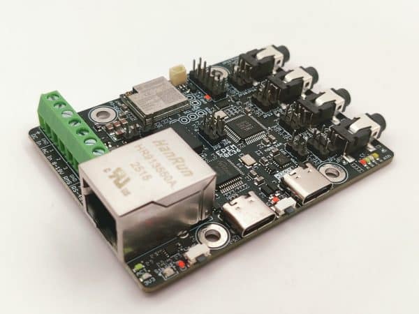
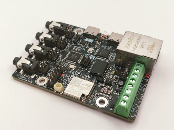
My design focus was to maintain the original IPEM board size of 85x55mm, maintaining mechanical compatibility, where possible, but also squeeze in:
- Ethernet Controller with Full TCP/IP Stack
- RJ45 Connector
- RS-485 Interface (MODBUS)
- DS3231DN RTC & Battery Backup Option
- Remove Solder Jumpers
In addition, although the board is multi-layer, I wanted to try and keep all SMT ideally to one side in order to keep the board mechanical skyline as low and compact as possible, this meant all standard passive components shrinking down to very small size and so including more features for the user.
MCU Change
All original IPEM boards and variants were based on the ESP32-WROOM.
With the advances in Espressif MCU technologies, moving away from the humble ESP32 to the newer ESP32-C6 provides increased speed advantage plus the superior and powerful radio with Zigbee, thread and mesh, so the move to using the ESP32-C6 in EPEM was an obvious choice. It also has a much smaller footprint, which is a big bonus.
Ethernet
For a while, users have been asking about possibility of adding Ethernet to the IPEM board, largely due to either the boards being mounted inside cabinets for example, or away from access points, and also for security or low power closed IoT systems.
The ESP32-C6 does not have an internal EMAC with MII/RMII (as with original ESP32), so I have opted to use the SPI interface to the popular WIZnet W5500 Ethernet Interface.
Radio and U.FL
With EPEM boards potentially going into metal, or shielded cabinets, or needing external antennas, aside from ethernet, the U.FL connection interest has also peaked.
As previously mentioned, the ESP32-C6 includes a powerful radio module, opening up a range of IoT applications that include:
Wi-Fi 6
- 2.4 GHz (2400 ~ 2483.5 MHz)
- 802.11ax (20 MHz bandwidth)
- 802.11b/g/n (20/40 MHz bandwidth)
- CE Max EIRP 19.81 dBm
Bluetooth
- 2.4 GHz (2400 ~ 2483.5 MHz)
- Bluetooth LE
- Bluetooth 5.3
- Bluetooth Mesh
- CE Max EIRP 18.46 dBm
Thread 1.4
- 2.4 GHz (2405 ~ 2480 MHz)
- 802.15.4
- Thread Mesh
- CE Max EIRP 10.29 dBm
Zigbee 3.0
- 2.4 GHz (2405 ~ 2480 MHz)
- 802.15.4
- Zigbee Mesh
- CE Max EIRP 10.40 dBm
Zigbee and mesh are expanding in an range of home, farming and industrial applications, so will be interested to see how this develops over time.
Using a mix of Ethernet and Zigbee, installations could offer remote mesh systems, with a mix of communications technologies.
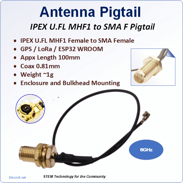
Tip: MHF3 Antenna Connection
The ESP32-C6-MINI-1U uses an IPEX MHF3 antenna connector (also known as IPEX3), which is much smaller than the standard commonly used IPEX MHF1, for example, on the ESP32-WROOM-32UE.
NB. This MHF3 connector, together with its very similar but different MHF4 variant, are commonly used on M.2 cards and laptop type Wi-Fi cards. The MHF3 and MHF4 connectors are not compatible as they are very so slightly different diameter and heights (mating depth).
RS-485
To interfacing to other Smart Meters, Devices and Smart Batteries which have an RS-485 MODBUS interface, the EPEM includes a standard industry interface which allows you to collect, or control, other devices on the RS-485 bus.
This RS-485 interface could also be used to control local CCTV on remote installations, or even send data from the EPEM board over a single twisted pair, up to around 1,200 meters (4,000 feet), in distance. Ideal for farms and remote installations.
Real Time Clock
The need to maintain a very accurate real time clock when metering, or logging, was requested by some users. Ideally battery backed up.
This feature was included on the IPEM PiHat and so I have included it on the EPEM too.
Using the same extremely accurate and low power DS3231SN real time clock IC, with integrated temperature compensated crystal oscillator (TCXO), this is easily controlled via I2C and maintained via external optional plug-in CR2302 3V coin battery.
Board Configuration
Earlier IPEM boards used solder jumpers and whilst these worked, I wanted to make it easier to configure the boards.
On the IPEM PiHat’s, I used DIP switches which worked well but these take up board space and are expensive. So on EPEM I have opted to use plug-in 2mm jumpers which give the best of both worlds.
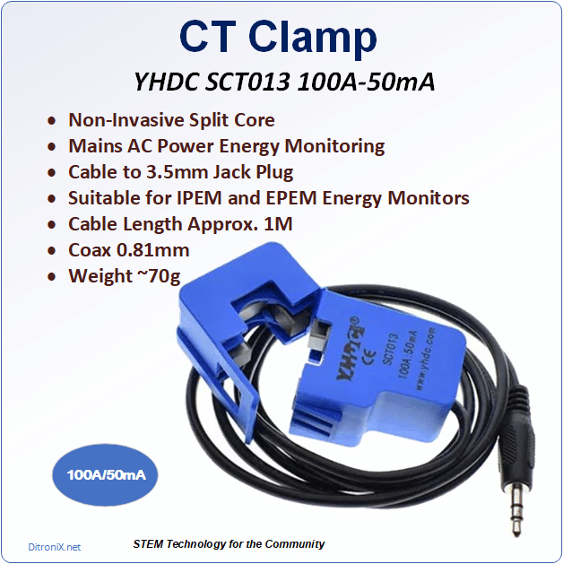
CT Clamps and Rogowski Current Transformer
EPEM was designed primarily for the standard CT clamp such as the YHDC SCT-013 100A-50mA. Inputs for each channel 1, 2, 3, plus N are via standard 3.5mm jack sockets.
You can also use Rogowski Current Transformers on any inputs. Each input is configurable using a jumper.
Mains Monitoring
All my boards are designed to be safe and easy to use – with NO live working, mains electricity parts or dangerous exposed high voltages.
The EPEM uses only low voltage 12 V AC such as from a bell transformer and clip on CT Clamps.
Electrical Circuit Types
The EPEM is capable of monitoring a number of variations in energy monitoring systems such as:
- Accurately monitors both Import and Export
- Single phase (Home, Office etc.)
- Multiple Single Phases. (Different circuits or home/office rings, Inverters etc.)
- Dual Phase (2 x Live -Typically for USA. i.e. 2 x 110V)
- Three Phase Star (3 x Live and 1 x Neutral)
- Three Phase Delta (3 x Live)
Data Output
Data provided from the EPEM can be extrapolated through your code in any way you wish, in order to easily integrate with your IoT Home Automation system, or Solar Installation monitor.
All software and code is open source, community based and allows you to develop and integrate as you wish.
The main process typically used for publishing data (internally or externally), is via MQTT, or you could use other direct publishing routes such as to Domoticz, Zabbix or Home Assistant.
Data from the ATM90E36 includes:
- Mains RMS Voltage (each phase)
- Mains Frequency (each phase)
- Import and Export Values
- Mains RMS Current
- Calculated RMS Power
- Active Power (Absorbed or Used by the Load)
- Calculated Total Active Power
- Re-Active Power
- Calculated Total Reactive Power
- Apparent Power (Total Amount of Power Flowing from Source to Load)
- Calculated Total Apparent Power
- Fundamental Power
- Harmonic Power
- Power Factor
- Phase Angle
Programming and Development
Development is primarily supported through Visual Studio Code (VSCode) and Arduino IDE. This also includes platforms like ESPHome.
A range of libraries are already available which support the devices on the EPEM such as the:
- ESP32-C6
- M90E36
- W5500
- 24C64
- DS3231
- TMP102
- WS2812
Code support is available in my existing GitHub IPEM and FLiX repositories, with a specific core EPEM code repository being provided as the board evolves, together with a new FLeX test and bring up firmware, which is in development.
This is a worldwide community project and is able to be integrated in so many systems.
 X.com/DitroniX
 LinkedIn.com/in/g8puo/
 Kickstarter
 Instagram.com/DitroniX.iot

Reviews
There are no reviews yet.