


Description
Overview
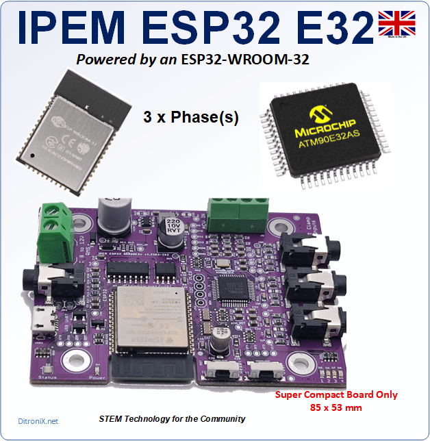
IPEM is a 3 phase (or Single, Split, 3 + 1 phase), high-performance Mains Electricity Energy Monitor. with ESP32, ATM90E32 or ATM90E36
This product is the ESP32 ATM90E32 Version
History
Following on from the GTEM ATM90E26 project, interest and feedback has been encouraging. The GTEM board design works very well and has received positive responses, however, with multiple inverters, the next challenge was to increase the number of inputs.
An enhanced board project, called IPEM, has been designed, based on an ESP32 integrated with an ATM90E32 (or ATM90E36), for direct 3 Phase, 3 x Single Phases or 1 x Split Phase (for USA), energy monitor. enhanced high-performance energy metering devices. These are complete current and voltages for each of the phases – fully user configurable.
Summary
- ATM90E32 or E36 Main Power Energy Monitor.
- Three Phase, or 3 x Single Phase Current Clamp.
- Single, Split or Three Phase Voltage Inputs.
- Separate CT4 interfaces to E36-IN or ADC-ESP32.
- AC Power 12V Input for Safety Which Provides Power to Board and AC Voltage Sensing.
- ESP32-WROOM-32 MCU (32E or 32UE).
- 24C64 EEPROM (Parameters, Logging etc.)
- USB Interface (Wemos D1 Compatible) UART Interface.
- NTC Temperature.
- User GPIO. OLED.
Features
With increased current sensor and AC voltage inputs, together with high dynamic range, the new IPEM board makes a good addition to the power energy monitoring projects.
Inline with my other MCU projects, I prefer the ‘complete’ board approach, where the ESP32 WROOM is included on the board, together with an EEPROM, for parameters and logging, plus a CH340 USB-UART, so providing ‘Wemos D1 Mini’ flashing, logging and debugging compatibility.
Safety, Safety and more Safety!
An important criteria of the Energy Monitor was the ability to safely and indirectly connect to mains, without working on high voltages.
For this reason, the board contains low voltage AC sampling and a DC power supply, both derived from a singe low voltage AC input.
The AC input should be safely derived from a SELV (Safety Extra Low Voltage), 12V transformer. This type of power supply, much like Bell transformers, provides total isolation from the mains as it features a lack of a return path, through earth.
The separate commonly used current clamp simply snaps over a single meter tail cable, so is safety isolated too.
Note: Most wall chargers are either DC output (which is no good) or PELV. To learn more about the differences of SELV and PELV, this video provides a good insight.
Logging and Parameters
Storing parameters ,settings and even local logs is always useful. All our boards include an AT24C64 (EEPROM 64Kb – [8K x 8] Memory IC ).
This is easily accessed via I2C and Arduino EEPROM libraries. The Non-Volatile memory allows for data to be retained, even when power is off. Examples being Wi-fi settings, calibration data etc.
Flashing, Programming and Debug Logging
To make it easier to connect using just a Micro USB cable, the IPEM board includes a CH340 USB-to-serial UART. This IC is commonly used on boards like the Arduino D1 mini, requires no drivers and makes programming and debugging from the Arduino IDE and Visual Studio Code / Platform IO easy.
Our SDKs are WeMos D1 Mini flashing compatible Set the BOARD to ESP32, ‘WEMOS D1 MINI ESP32’ DEV Module (or similar). You can also set the BAUD rate to 921600 to speed up flashing. The SDK does NOT need external power to flash. It will take Power from the USB 5V. You will need to provide external 12V AC for power up of the Energy Monitor functions. You will need to provide a CT Current Clamp. Ideally YHDC SCT-013-000
All test code is OPEN SOURCE and although is is not intended for real world use, it may be freely used, or modified as needed. It is distributed on an “AS IS” BASIS, WITHOUT WARRANTIES OR CONDITIONS OF ANY KIND, either express or implied.
Versions
Two versions of the ESP32 was available. Espressif (ESP32-WROOM-32E-N4 Internal PCB antenna and ESP32-WROOM-32UE-N4), external Antenna via the IPEX U.FL)..
Further detail on my GitHub Wiki.
Further improvements to the design includes the ability to use the forth CT input on the ATM90E32 version. This has been achieved by allowing the port to be mapped via solder jumpers, to the ESP32 ADC.
 GitHub/DitroniX
 X.com/DitroniX
 YouTube.com/@DitroniX
 LinkedIn.com/in/g8puo/
 hackster.io/DitroniX
 Kickstarter
 Instagram.com/DitroniX.iot


Reviews
There are no reviews yet.